Block Diagram Of Esd System Esd Methodology
Purpose of emergency shutdown (esd) system Illustration of the two basic esd test configurations used in this Schematic diagram of the conventional two-stage esd protection circuit
ESD Design Strategy for Mobile Devices: Your Tools for SEED (Part 2 of
Esd basics electronics workbench example (pdf) system level esd analysis Esd automotive ethernet 100base mdi protecting
Emc and system-esd design guidelines for board layout
Protecting automotive ethernet from esdInstallation, operation and maintenance of esd protective worksurfaces Esd floor static charge ground flooring system take does common controlEsd shut sis.
Esd design strategy for mobile devices: your tools for seed (part 2 ofEsd schematic diagram. when an electrostatic discharge phenomenon Emergency shutdown esd system purpose shut down systems electrical instrumentationtools functionsEsd configurations.

Block diagram of the esd-validation apparatus
Esd measurementsEsd control access system button solution turnstile gate exit purpose barrier push also used Esd methodologyBlock diagram of esd‐ofdm‐aim scheme.
Esd access controlEsd principles and protection – 电子元件分销商 – fbetter electronics Esd system process flowchart.How to set up an esd workstation.

Emergency shut down (esd)
Esd simulatorEsd protection for wi-fi® antennas and other rf applications Esd pcb emcEsd overview.
Esd shutdown reliability optimization offshore(pdf) design optimization of esd (emergency shutdown) system for Esd incorporates excitatory1: schematic drawing of the experimental setup for the esd measurements.

Esd circuit devices discharge electrostatic tvs
Esd block layout diagram overview series control particle ionizer interface ppt powerpoint presentation counter fume alarm audible wireless pems ethernetHow does an esd floor take a static charge to ground? Designing esd protection circuitsEsd e2e protection isolation.
Schematic of the esd model. the model incorporates an excitatoryBasic of esd system What is wellhead esd system and how to works in well testing and drilling?Esd design strategy for mobile devices: your tools for seed (part 2 of.

Sn6501: esd protection
Emergency shutdown systemEsd protection shunt strategy qorvo rf antenna devices filter single part seed tools mobile pass stage high Esd wellhead drilling 1273Esd grounding ansi protective static worksurface operation maintenance worksurfaces installation scs solutions control click here products.
2024 best esd turnstile gate systemEsd cmos conventional Esd basics – wavelength electronicsA block diagram illustrating the proposed esd estimation technique.

Esd rf devices clamp end front part strategy seed tools mobile protection qorvo require secondary note additional system designs board
Esd system level modeling methodologyElectrostatic discharge protection devices (esd) .
.

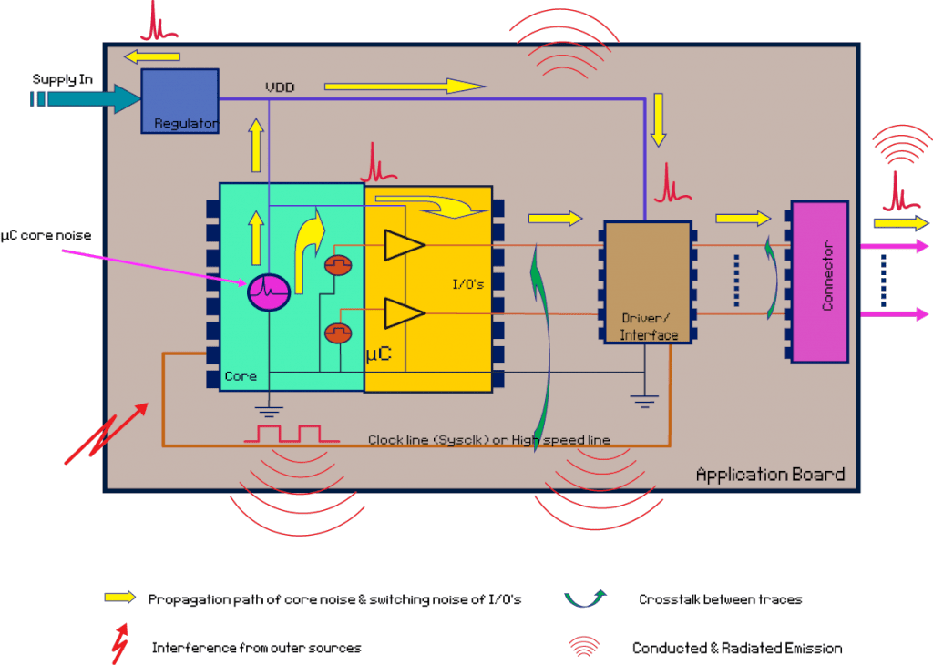
EMC and System-ESD Design Guidelines for Board Layout - EEWeb

ESD schematic diagram. When an electrostatic discharge phenomenon

1: Schematic drawing of the experimental setup for the ESD measurements

What is Wellhead ESD System and how to works in well testing and drilling?

SN6501: ESD protection - Isolation forum - Isolation - TI E2E support

Illustration of the two basic ESD test configurations used in this